Resistance Thermometer Detectors (RTD’s)
The resistance that an electrical conductor exhibits to the flow of an electric current is related to its temperature, essentially because of electron scattering effects and atomic lattice vibration. the basis of this theory is that free electrons travel through the metal as plane waves modified by a function having the periodicity of the crystal lattice. the only little snag here is that impurities and what are termed lattice defects can also result in scattering, giving resistance variation. fortunately, however, this effect is largely temperature- independent, so does not pose too much of a problem ; we just need to be aware of it.
In fact, the concept of detecting temperature using resistance is considerably easier to work with in practice than is thermocouple thermometry. firstly, the measurement is absolute, so no reference junction or cold junction compensation is required. secondly, junction or cold junction compensation is required. secondly, straightforward copper wires can be used between the sensor and your instrumentation since there are no special requirements in this respect.
IEC 60751: RTD Standards And Tolerances
For the purposes of the IEC 60751: 1983 (BS EN 60751: 1996) standard, the RTD itself comprises the sensing resistor within its protective sheath (if applicable), internal connecting wires and external terminals for onward connection. Mounting equipment and connection heads can also be included. IEC 60751 actually applies to industrial devices, primarily sheathed, over the temperature range
-200°C to 850°C, and offers two tolerance classes, A and B – these defining the maximum deviation in degrees Celsius from the nominal temperature relationship table figures. Class A RTD’s can show deviation of ±0.06 ohms (±0.15°C) at 0°C, while class B sensors can be within ±0.12 ohms (±0.3°C) at 0°C.
Standard thermometers are constructed from platinum having an α coefficient of 3.85× 10⁻³/°C, and have nominal resistances of 100 ohms or 10 ohms at 0°C, the latter harnessing heavier gauge wire, and being aimed at use in the range above 600°C. with 100 ohm devices, Class A only applies up to 650°C; also the A classification is not applicable to two wire devices. Clearly, devices which conform to the standard as defined can be interchanged – always useful! See the reference and tolerance tables in this guide.
The standard also covers a range of other factors- but not construction. For example, the RTD’s have to be suitable for DC and AC current measuring systems – the latter up to 500Hz. So there are certain inductance and coupling constraints on design. Insulation resistance, response times, self-heating effects, immersion errors, thermo-electric effects, tests for temperature limits and temperature cycling, mechanical vibration and pressure effects are also specified.
IEC 60751 also says that manufacturers can reveal electrical characteristics, like thermometer capacitance, capacitance to earth, and inductance, as well as the ohmic resistance of the internal connecting wires. Also, calibration immersion depth, minimum usable depth, thermal response time and self-heating effects can be stated.
To download the catalog of this product, please click here.
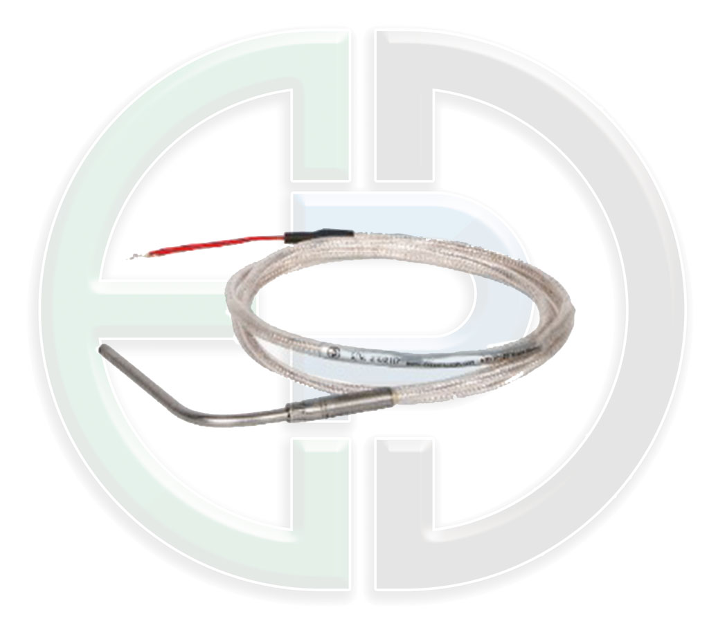
RTD
RTD
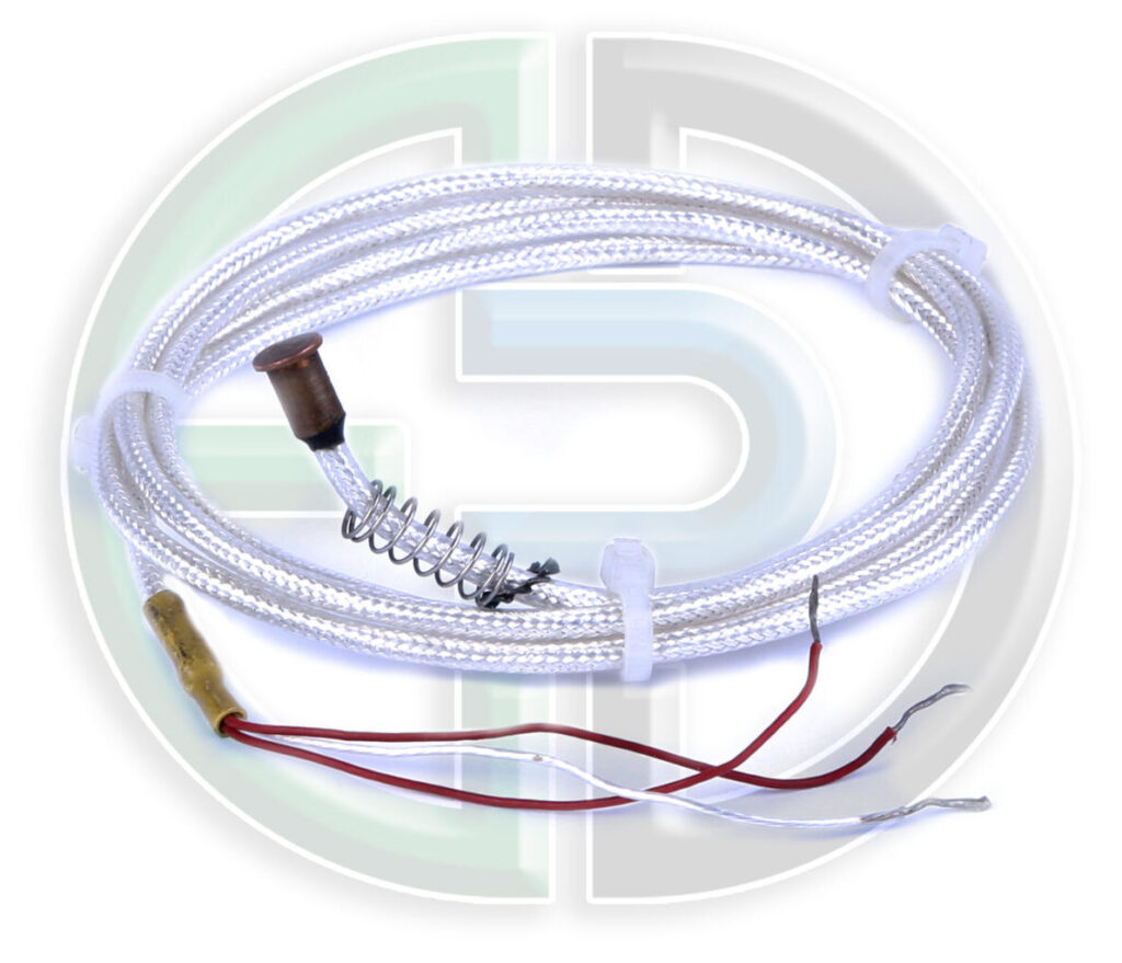
RTD
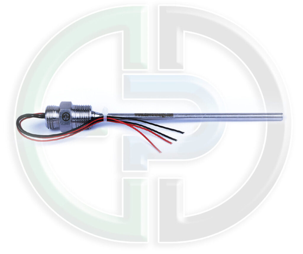
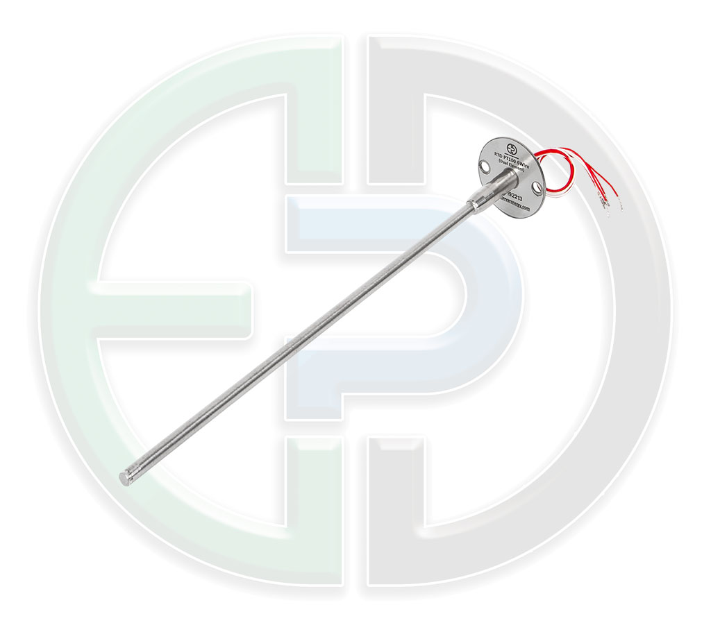
RTD PT 100,6WIRE ( DUAL ELEMENT)
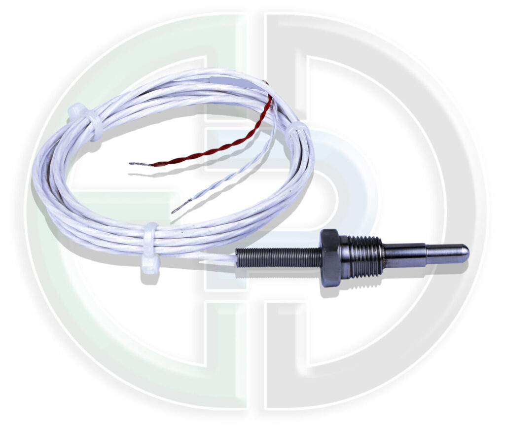
RTD PT100 ( SINGLE ELEMENT)