Proximity Systems
Proximity Systems Are Used to Measure the Static and Dynamic Distance Between the Object and The Probe. Petro Davvar Energy Pajohan Proximity Probes Measure the Following:
- Radial vibration.
- Axial thrust position Vibration
Our proximity probe system’s designed under API 670 standard. Each system consists of a probe, extension cable, and a proximitor.
Our Proximity Systems are Fully Replaceable With Vibrometer & Vibran & Bently Nevada 7200, 3300 And Metrix Products.
Components of proximity probe transducers
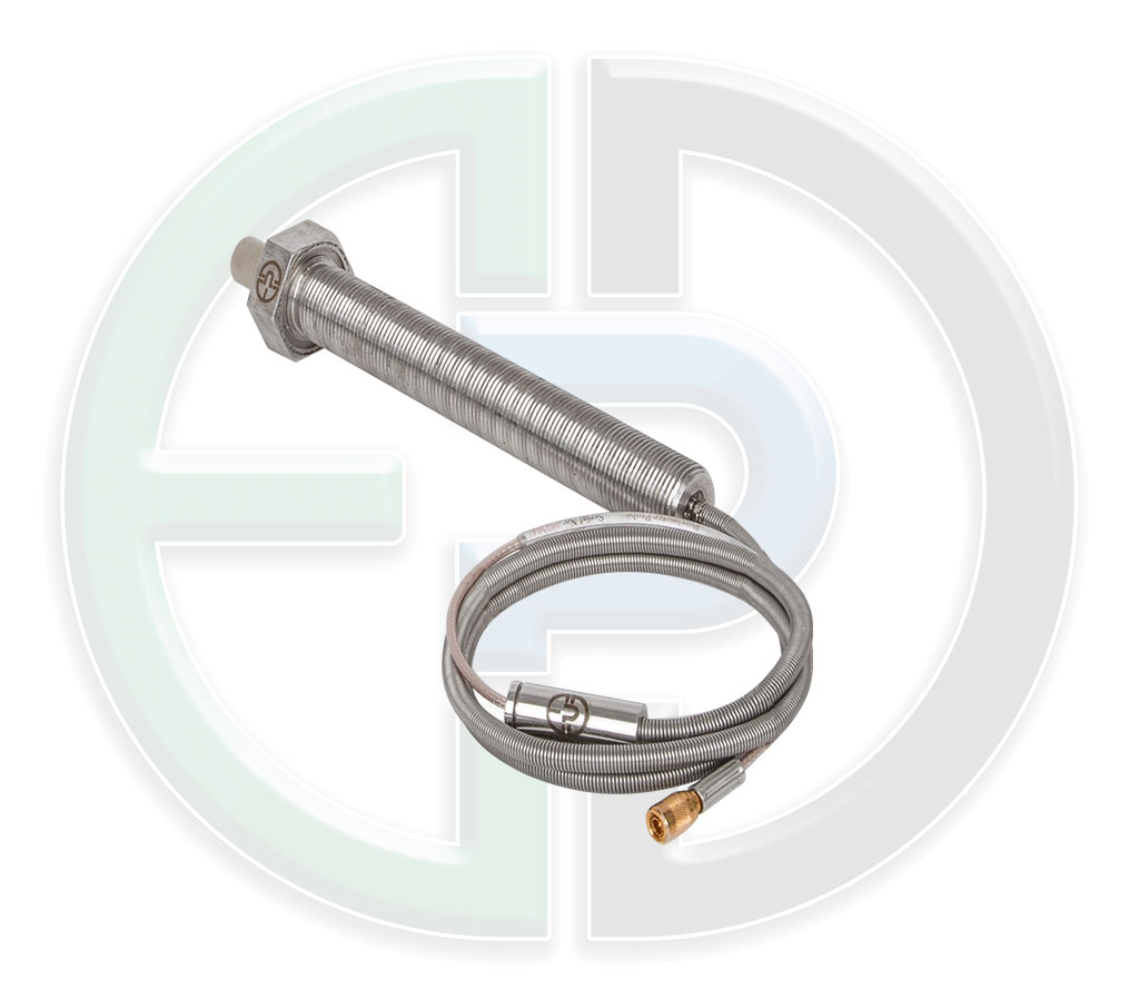
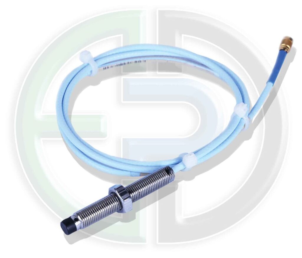
- Probe
The PDS probes are designed for long life cycles, probe and extension cable are equipped with rubber which covers the connectors and prevents oil and dirt penetration. Our probes are compatible with 5& 9 meter systems.
- Extension Cable
Our extension cable Model PDEC design results in better system performance and a longer life cycle.
The total length of the probe and the extension cable need to be 5m or 9m in total length.
The connector on the extension cable is also an API 670 Standard, allowing compatibility with other manufacturers’ proximity probe systems.
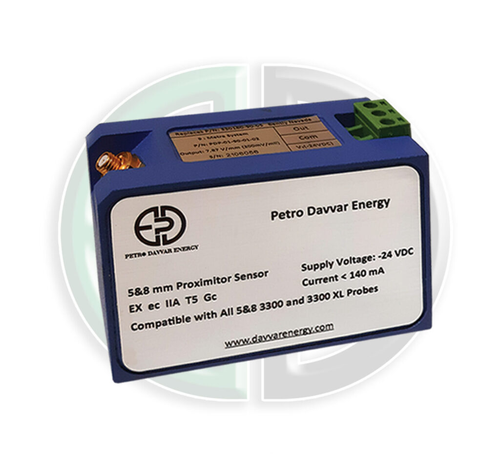
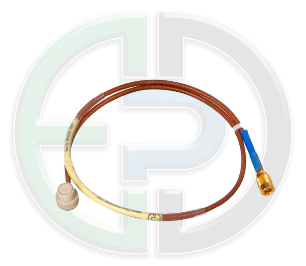
- Driver
The PDP driver is used for our proximity probe systems. The total length of cable between the probe and the driver should be 5m, or 9m.
EX Protection
Our probe, proximitor and extension cable have EX ecIIA T4 approvals by EPIL CO.
System Specifications
Electrical
Power Supply:
Voltage: -18 t0 -24 VDC
Current: < 20mA
Linear Range: 2.0mm (80mils) begins at 0.25mm (10mils) from probe face (AISI 4140)
Range is 0.25 – 2 (10 – 80 mils)
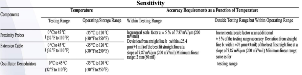
a) The incremental scale factor (ISF) error is the maximum amount the scale factor varies from 7.87 mV/µm (200 mV/mil) when measure at specified increments throughout the linear range. Measurements are usually taken at 250 µm (10 mil) increments. ISF error is associated with errors in radial vibration and axial position readings.
b) The deviation from straight line (DSL) error is the maximum error (in mils) in the probe gap reading at a given voltage compared to a 7.87 mV/µm (200 mV/mil) best fit straight line. DSL errors are associated with errors in axial position or probe gap readings.
Instruction:
Field Wiring: Use 0.2 to 1.5 mm2 (16 To 24 AWG) 3 Conductor Shielded Wire. Recommended Gap Settings is Approximately 9 VDC (Approximately 1.3 mm Or 55 Mils). Frequency: 0 To 10 KHZ.
Minimum Target Size (Shaft Diameter): 50.8 mm Or 2 Inch. Probe Tip Material: Poly Phenylene Sulfide (PPS).
Maximum Tensile Strength Probe Case To Probe Lead Should Be 300 N. Maximum Tensile Strength Probe Lead To Extension Cable Should Be 250 N.
Maximum Probe Case Torque: 21 N.m. Maximum Connector Torque: 0.5 N.m. All Connectors Are Finger Tighted.
The Proximitor Should Be Installed In Cool Box With at least IP54 Protection Because of Terminals the box should be electrically earthed.
All connections, terminals, earthing and calibration of system should be checked permanently. The maximum tensile force is 5 N for input and output terminals and 100 N for cable, probe and proximitor.
Dielectric Test:
When supplied with terminals complete of wiring cables, the equipment have been. Submitted to the dielectric test in accordance with the clause 7.1 of EN 60079-7 with. The following values: 500 V r.m.s
Environmental:
Probe Driver Temperature Operation: -40°C to +80°C Probe Temperature:
Operation/Storage: -40°C to +177°C Extension Cable Temperature: Operation/Storage: -40°C to +177°C Humidity: 100% non-condensing
- Bently Nevad 3300 & 7200
- Metrix 3000 & 1000
- Vibro Meter Iqs402 & TQ412/IQS450 & IQS452 (meggit)
To download the catalog of this product, please click here.
Proximity
Extension Cable
probe
Finger Probe
TQ Probe